
 English
 русский
 Español
 Deutsch
 عربى
 italiano
 中文
Instrumentation Selection Guide
The flow reading and the pressure reading belong to the same system. Here is how to specify them together, without over-specifying.
An aeration line at a small water treatment plant shows 40 percent flow on a panel-mounted rotameter, while the plant computer, working from a pressure-derived calculation, reports the line as nearly empty. The maintenance engineer finds no leaks and finally reads the nameplates: the rotameter scale is calibrated for air at atmospheric pressure, and the pressure gauge is ranged to 25 bar for a line that never exceeds 3.5 bar. Neither instrument is broken. They were simply specified for different conditions.
The air flow pressure meter, in most industrial settings, is not a single instrument but a pair — a flow meter and a pressure gauge — that must be selected as one system. When the media, range, and accuracy are defined together from the start, installation, calibration, and daily reading all become more predictable.
Start with the Media and the Range, Not the Model Number
The most common specification mistake is opening a catalog before defining the fluid. Air is compressible, and its density changes with temperature and pressure. A glass rotameter scaled for air at 20 °C and 101.325 kPa gives a meaningful reading only when the line operates near those reference conditions. The same meter on a warm compressor discharge line will indicate differently, even though the mass flow has not changed.
Before discussing model numbers, collect these values:
- Fluid: air, nitrogen, oxygen, carbon dioxide, argon, or a mixed gas.
- Flow range: normal, minimum, and maximum values, with units stated as m³/h, L/min, SLPM, or Nm³/h.
- Operating pressure and maximum permissible overpressure, with units in bar, MPa, or psi.
- Media temperature, plus ambient temperature when the meter will be enclosed in a panel.
- Connection size and type: thread, flange, tri-clamp, or hose nipple.
Once these five points are written down, the family of suitable instruments narrows quickly.
Compare the Measuring Principles Before You Commit
For air and gas service, most engineers choose among four families. Variable-area rotameters are simple and economical; differential pressure systems are traditional and widely understood; thermal mass meters measure airflow directly in mass units; vortex meters perform well in larger, cleaner streams. Each has a different strength, and the table below summarizes the practical differences that affect selection.
| Measuring principle | Typical air/gas application | Typical accuracy | Output available | Main limitations |
|---|---|---|---|---|
| Variable-area rotameter | Clean, dry air; low to moderate pressure; small lines and panel mounting | Class 2.5 for glass tube; 1.5–2.5 for metal tube | Local scale; optional alarm contacts; 4–20 mA with transmitter | Vertical installation required; density-dependent; about 10:1 turndown |
| Differential pressure | Medium and large pipes; existing orifice plate runs | Roughly 1–2 % of span, transmitter-dependent | 4–20 mA, digital | Permanent pressure loss; straight upstream run needed |
| Thermal mass | Compressed air; dry gases; low-flow analysis | 1–2 % of reading, typical | 4–20 mA, digital | Sensitive to moisture, oil mist, and coating |
| Vortex | Clean air or gas; mid-to-high flow; larger pipes | 1–2 % of reading, typical | 4–20 mA, pulse | Minimum velocity required; avoid strong vibration |
The most accurate principle is not always the right one. A thermal mass unit delivers excellent data but demands dry, clean gas. A differential pressure system is well understood but adds a permanent pressure loss. For many plants, the variable-area rotameter is accurate enough for the purpose, requires no power, and is the easiest to verify in the field.
The Rotameter Remains a Practical Default for Air
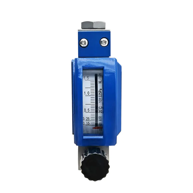
For clean, dry air at low to moderate pressure, the variable-area rotameter is still the most direct solution. It needs no external power, shows the flow instantly on a local scale, and can be checked against a reference meter without complex setup.
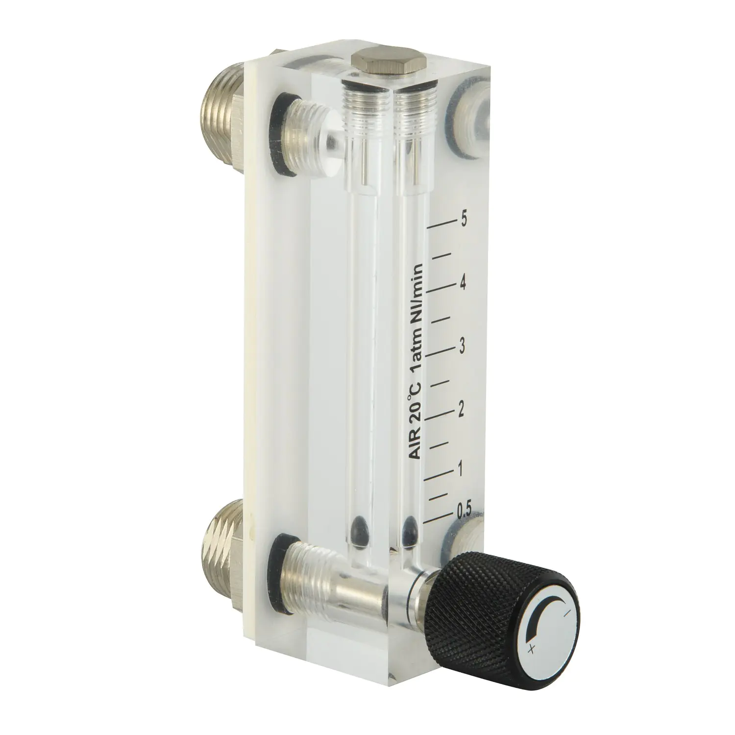
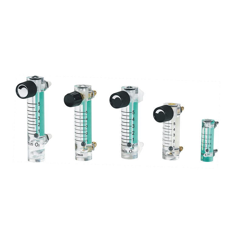
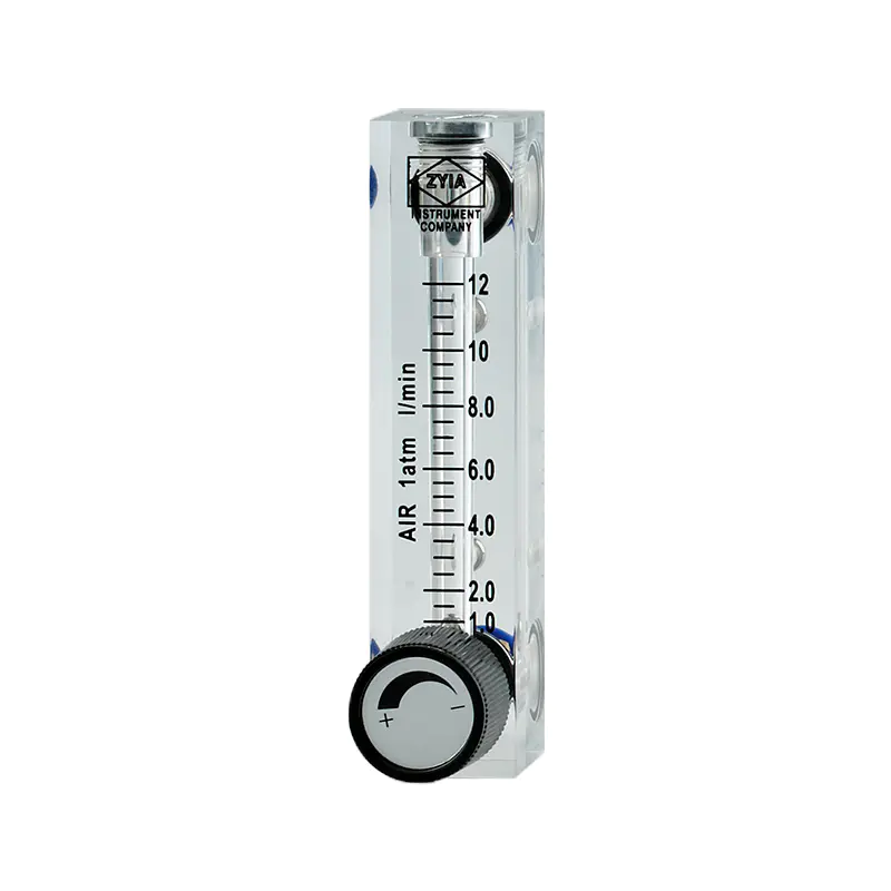
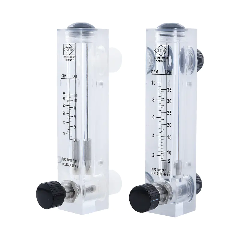
Acrylic tube rotameters, such as the LZM6T series used for argon and carbon dioxide lines, cover panel-mounted gas service, analyzer sample systems, and small process skids.
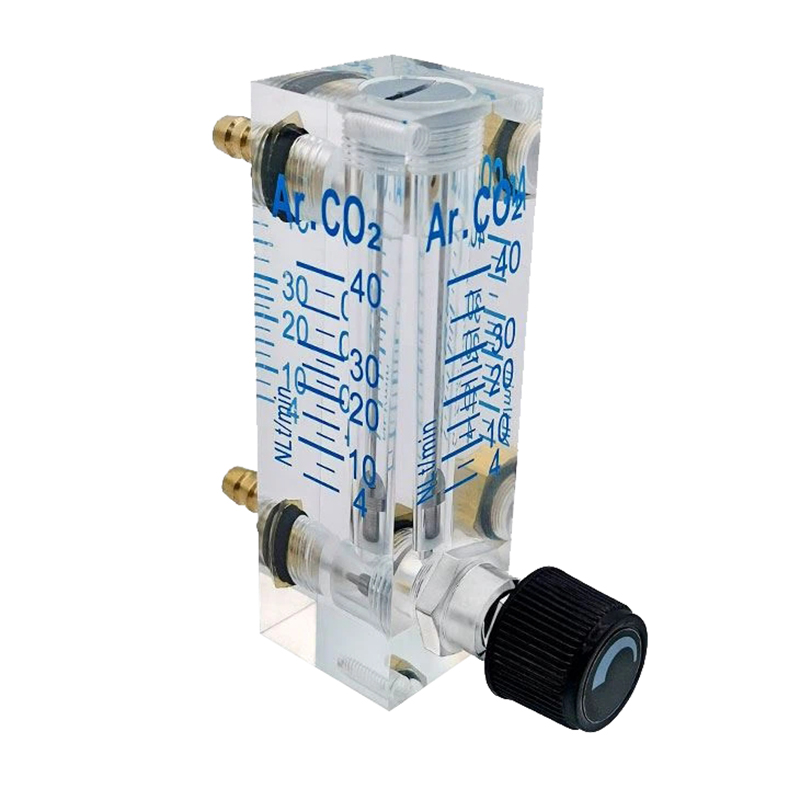 LZM-6T Acrylic Rotameter for Argon and Carbon DioxideThis acrylic rotameter handles argon and CO2 in panel-mounted gas service, analyzer sample systems, and small process skids; its transparent tube makes it the acrylic representative in the rotameter family.View Product →
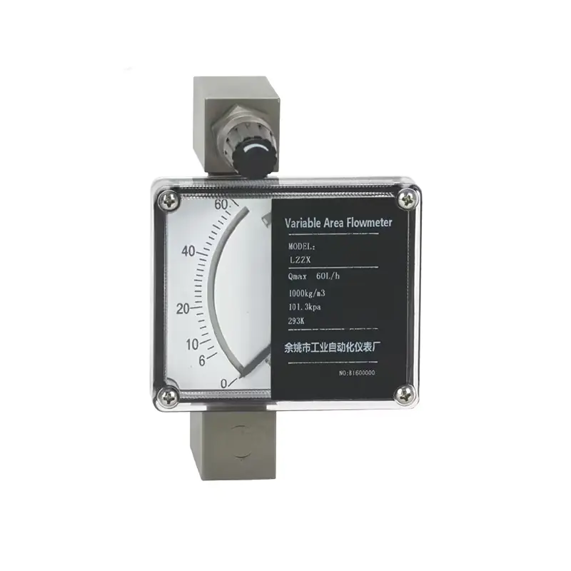
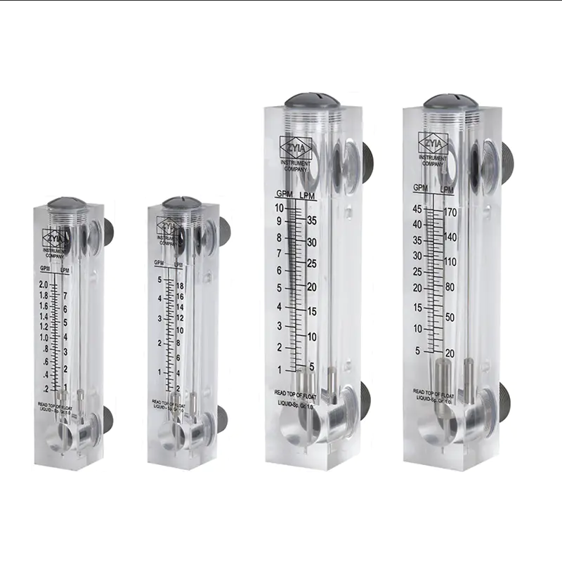
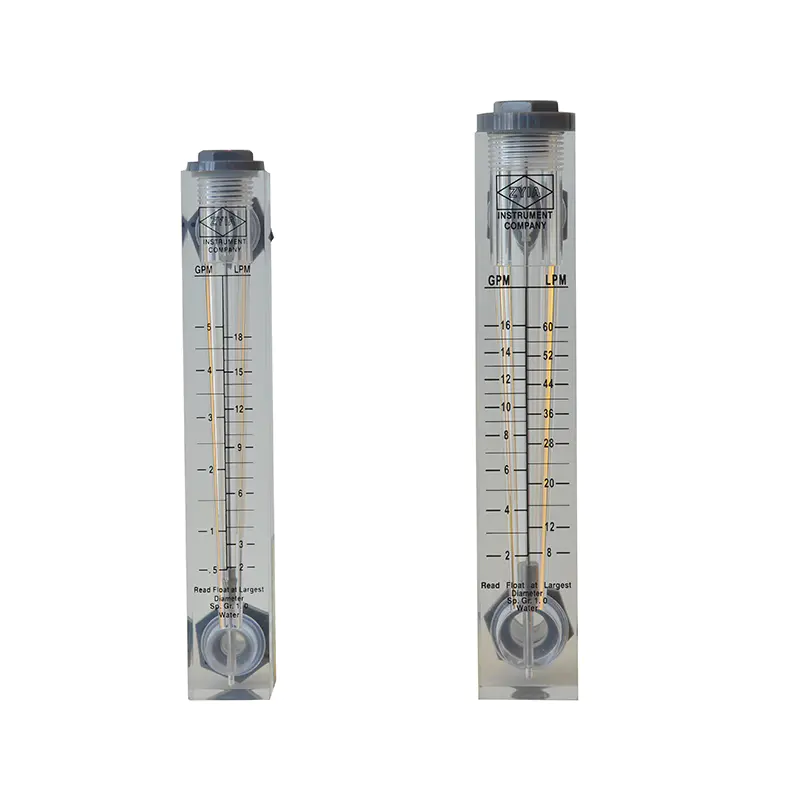
Glass tube versions add chemical resistance; metal tube rotameters handle higher pressures and can carry a transmitter for remote reading. Our full flow meter range extends through glass, acrylic, metal tube, and plastic tube designs, so the practicality of the rotameter family is not limited to one material.
Read the scale at the center of the float. Install the meter vertically, flow upward. A float calibrated for air cannot simply be reused for a heavier gas on the same printed scale.
The Pressure Gauge Is Half of the Measurement Pair
Flow data without pressure data leaves a system half-diagnosed. A blocked filter, a worn compressor valve, or a partially closed isolation valve all change line pressure before flow changes. A dependable pressure gauge turns the flow reading into a usable diagnosis.
Bourdon tube pressure gauges are the standard for compressed air and gas service. The YTN series gas pressure gauges are built for this duty with steel or stainless steel cases, and liquid-filled versions damp vibration from reciprocating compressors.
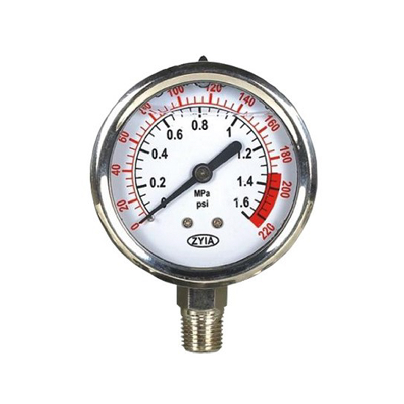 YTN-Series Liquid-Filled Gas Pressure GaugeThis YTN-series gauge uses a Bourdon tube with steel or stainless steel cases; liquid-filled versions damp compressor vibration. When selecting a range, place normal pressure near the middle third of the dial for clear indication.View Product →
Range selection matters as much as the movement itself. For a line operating at 6 bar, a 0–10 bar gauge provides the clearest indication. The normal operating pressure should sit near the middle third of the dial; at either extreme, readability and accuracy class degrade. For a deeper walkthrough of range matching, see our air flow pressure meter selection guide.
Add Alarm Contacts or a Signal When the Process Requires It
Local indication solves the visibility problem but not the response problem. If a nitrogen purge line must alert the control room when flow drops, or a compressor must shut down on rising pressure, the instruments need electrical contacts.
Many variable-area meters can be ordered with integrated alarm limit switches on the tube. The gas flow meter with alarm, for example, triggers when flow falls below or rises above a preset point, while electric contact pressure gauges switch at adjustable set points for pump and compressor protection.
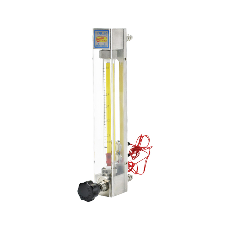 Gas Flow Meter with Alarm Limit SwitchesThis gas flow meter with built-in alarm switches signals at high and low flow limits, giving local alerting for variable-area gas service; useful when a simple threshold is required before considering remote transmitter options.View Product →
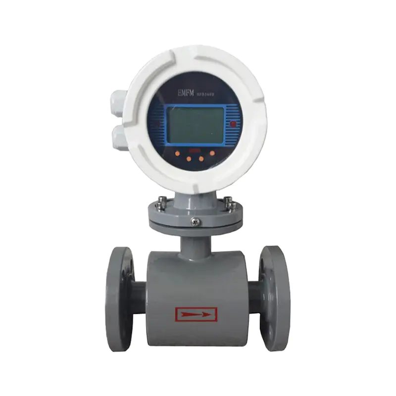
When a continuous signal is required, metal tube rotameters with a 4–20 mA transmitter provide remote flow indication without switching to a different technology. For conductive liquids such as wastewater, an electromagnetic flow meter is the better route; for air and gas, the variable-area family covers most needs without added complexity.
Installation and Procurement: What to Verify Before Signing
Even a correctly specified air flow pressure meter can cause trouble in the field when installation details are ignored. The checklist below covers the points that generate the most service calls.
- Mount rotameters vertically with flow upward, and avoid placing them directly after a control valve.
- Confirm the connection size and type against the existing pipework: thread, flange, clamp, or barb.
- Select the pressure gauge scale so the normal working pressure sits between 25 and 75 percent of full scale.
- Check seal, float, and tube material compatibility with the media, including any cleaning agents.
- Keep transparent acrylic and glass tube meters away from solvents and from any condition that exceeds the working pressure rating.
- Request the calibration certificate and confirm verification according to JJG257-2007, the verification regulation for float flowmeters.
On the procurement side, a stamped nameplate showing media, scale, pressure rating, and serial number is not a luxury. It is the first checkpoint during acceptance and the only reliable way to trace performance later.